Linux kernel module : Building a soft UART for the Raspberry Pi - part1
The RPi is a well-known
platform intended for educational use. For its compact form and
relatively low cost, this board has become very popular among
enthusiasts and makers. The RPi is used in many projects from different fields, eg.Robotics,
IoT… where it’s linked with
different types of sensors and detectors.
In many cases, the sensors that are used, adopts a communication
protocol such as SPI, UART, I2C for wired communication, or wireless using protocols
such as Bluetooth and ZigBee. The most adopted, and
easy to use of serial protocols is the Universal Asynchronous Receiver-Transmitter (UART for short).
Unfortunately, all versions of the RPi until version 3, comes with only two UART ports: A full featured UART (PL011)
enabled by default (GPIO’s 14 and 15), and a mini
UART with a reduced feature
set (used by the wireless LAN/Bluetooth controller, on models which
contain this controller) that necessitate some tweaking to get it
working at first (modification of the Device Tree Overlay basically).
This hardware limitation of the RPi can be a complication for projects that needs more
than the two UART ports,
especially for RPi models that
doesn’t have much of peripherals (eg. RPi Zero).
The idea behind this project, comes to tackle this specific problem by
creating a software UART
compatible with all Linux based boards including the
RPi. Because it’s a software
implementation, it has only the minimal features required to establish a
reliable serial connection. As you will find throughout this 2-parts
write up, the software implementation obviously can’t compete with the
real hardware port, nevertheless, it offers a decent alternative.
All the code can be found in my Github.
Linux driver
Yes, I opted to implement this software UART port inside the Linux kernel as a Linux driver
(a.k.a Linux module). If you are not familiar with Linux modules, they
simply consist of a chunk of code that runs inside the kernel space,
basically to add useful features to the OS or support to some device or
user app, and it can be loaded/unloaded into the Linux kernel at
runtime. The advantage of Linux modules over the applications that runs
in the user space, is that they have higher execution privilege and
generally run’s faster than the user space apps. As we are trying to
emulate a hardware protocol by software, speed of execution is a real
concern for us, hence, the implementation as a Linux driver.
UART serial port
Before starting the implementation of our driver, we need first to take
a look at the inner working of the UART protocol.
Below is a general summary of how the UART protocol works.
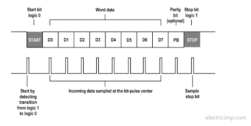
The UART protocol is a
two-wire protocol: transmit Tx
and receive Rx, that lets two
nodes exchange data asynchronously. To synchronize data sampling, the
transmitter adds to each data word a start and a stop bit (the stop can
be 1, 1.5 or 2 bits long), along with an optional parity bit that helps
protecting the integrity of the data word.
Each packet contains a data word that can be 5 to 9 bits long. When the
receiver detects the start bit in the Rx line, it starts sampling the
data at the frequency specified by the baudrate (bits/sec).
Additionally, advanced UART’s
implements a hardware flow control (HFC) which is basically a strategy
for communication between slow and fast devices without data loses.
UART is a very simple
protocol, however, its software emulation rises some exclamation marks
about software preemption and the execution speed. As a matter of fact,
like all other programs that runs on the processor, our Linux driver
will obey to the scheduling policy of the Linux OS and depending on the
baudrate used, the UART
protocol can impose very strict timing constraints: Each bit that is
transmitted via the Tx line, takes 1/baudrate seconds to be sent. Therefore, if we consider that
the receiver samples the data bits exactly at the middle,
1/(2*baudrate) will correspond
to the maximum allowed difference between the sender’s and the
receiver’s baudrates, e.g. for a baudrate of 9600, the max allowed difference between the two
baudrates is ~52 μs.
As a consequence, to avoid preemption and speed problems, in our implementation we will try to minimize all critical parts in the code and we will consider only the following minimal feature set of the protocol:
- Data word size of 8bits.
- 1 start and 1 stop bit.
- No parity bit.
- No flow control.
What is a Linux TTY driver?
The name of tty devices came
from the old abbreviation Teletype (writer), and it is commonly
associated with serial devices. For a serial port to be properly
integrated under the Linux kernel, it must be visible as a
tty device from the user
space, and for that, any serial driver must be implemented in the
tty kernel subsystem.
The figure below, shows the implementation of the
tty subsystem under the Linux
kernel:
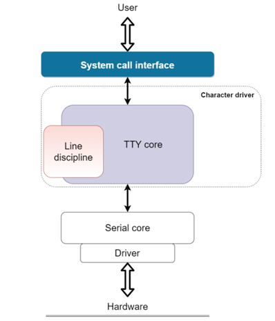
The tty core driver is implemented as a character driver under the
Linux kernel, and it offers a set of functionalities that serves as an
interface for serial devices. This driver is responsible of controlling
both the data flow and the format of packets passing through it,
allowing serial drivers to focus on the low-level hardware interactions
instead of worrying about data exchanges with the user space. In
addition, tty core include a set of extensions called ‘lines of
discipline’ that mounts between the tty core and the serial driver
enabling extended functionalities to the serial driver (by default,
tty core uses
ldscp N_TTY which directly
link the serial driver to the user space).
Until version 2.6 of the Linux kernel, serial drivers were implemented
directly under the tty core
driver inheriting a non-negligible complexity for the driver
development. However, since version 2.6, a new interface, serial
core, was implemented under the tty core to ease the
development of serial drivers.
In this project we will implement our driver under the serial core
interface, but before that, one of course must have a functional and
structural understanding of the APIs offered by this interface and how
interactions with the low-level operations Tx & Rx are implemented. For
that, one needs to analyze the source code of the interface:
/linux/serial_core.h .
After thorough analysis, in the diagram below I show the important structural links of serial core with the top layer tty core and the low-level layer:
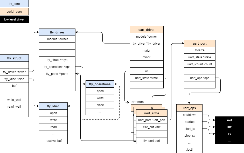
In fact, the use of serial core interface needs the definition of three main structures:
-
The structure representing the driver:
struct uart_driver -
The structure representing the port included in the driver:
struct uart_port -
The structure containing the pointers to the port operations:
struct uart_ops
Other structures are automatically initialized when the driver is registered on the kernel, and they must not be defined by the user e.g. tty_driver
Implementation
For organization purposes, (As we – informaticians – like to split things into layers) the implementation of the driver will be separated in two halves:
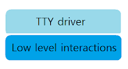
- A bottom half that contains the
UARTprotocol implementation and manages the low levelGPIOinteractions. - A top half which implements the actual
ttydriver and manages the interaction with the user space.
Before creating the code for the two layers, we first need to have some
sort of FIFO memory to store
received and to-send data. For this purpose, we decided to implement a
circular buffer that will manage data exchanges between the two layers
of the driver. Also, this type of buffer allows an efficient use of the
fixed buffer size.
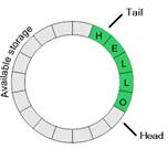
A circular buffer is characterized by two pointers that manages the read/write operations: a head pointer, always pointing to the top of the buffer (address of the next write), and a tail pointer that always points to the last element of the buffer (address of the next read).
In circular_buffer.h we will
create the structure of our circular buffer which include the two
pointers head &
tail, a fixed size data buffer
(of type char) plus a flag to
indicate the status of our buffer:
 struct buffer
 {
 int head;
 int tail;
 bool isfull;
 unsigned char data[BUFFER_MAX_SIZE];
 };
There will be two instantiations of this buffer:
rx_buffer and
tx_buffer so that data
exchanges can be managed separately between the two halves of the
driver.
In addition, we will define some basic functions that eases buffer manipulations:
-
The
initfunction that resets the buffer pointers to zero:void initialize_buffer(struct buffer* buffer); -
Functions to read and write one char into the buffer:
int push_character(struct buffer* buffer, unsigned char character);
int pull_character(struct buffer* buffer, unsigned char* character);
after each write (read) the
head(tail) pointer is incremented. This modification of the two pointers is implemented carefully following the circular buffer algorithm. -
Functions to get the status of the buffer:
bool isBufferFull(struct buffer* buffer);
bool isBufferEmpty(struct buffer* buffer);
Bottom half
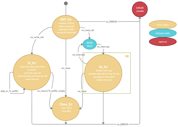
Now, let’s start our implementation of the low-level
UART protocol. To make things
more fun, I drew the state diagram below to sum up our implementation.
As it’s only a half-duplex protocol, our code will have only one
function to execute at a time: write or read.
In a new file soft_uart.c we
start the definition of our main functions:
INIT_fct:
The first function is the init
function, in which we start by initializing the Rx and Tx buffers, the
GPIO pins (note : the idle
state of the Tx pin is high), and we reserve the Rx line interrupt to be
able to start receiving data (in the ISR) asap. We initialize also a reception
tasklet that is used to pass
Rx data over to the top layer (this will be discussed further below).
This function takes in parameters the GPIO pin number of both Tx and Rx (in our implementation
we used pins 17 and
27 respectively), in addition,
it takes a pointer to the serial port structure
struct uart_port which is
handed over to the receiving tasklet.
For the baudrate, we will set it as a global variable so it can be accessed by all functions of the driver.
int uart_init(const int tx, const int rx, struct uart_port *port)
{
int ret;
/*Initilize buffers*/
initialize_buffer(&tx_buffer);
initialize_buffer(&rx_buffer);

/*Initialize the GPIO pins.*/
gpio_tx = tx;
gpio_rx = rx;
ret = gpio_request(gpio_tx, "uart_tx");
if(ret<0)
ret = gpio_direction_output(gpio_tx, 1);
if(ret<0)
ret = gpio_request(gpio_rx, "uart_tx");
if(ret<0)
ret = gpio_direction_input(gpio_rx);
if(ret<0)

/*Initialize interrupt: rx trigger*/
ret = request_irq(gpio_to_irq(gpio_rx), (irq_handler_t) handle_rx_start, IRQF_TRIGGE
R_FALLING, "Rx_handler", NULL);
if(ret<0)
else printk(KERN_INFO "irq requested succesfully ! \n");

/*rx_tasklet init*/
tasklet_init(&rx_tasklet, rx_tasklet_function, (unsigned long) port);
return 0;
}
Tx_fct:
The transmit function is implemented as a simple while loop in which we retrieve data – word by word – from the Tx_buffer and send it bit per bit, along with a start bit at the beginning and a stop bit at the end of each data word.
To respect the baudrate, we will implement a delay after each bit that
is sent using the ndelay()
function (nano-second delay). In addition, at the end of transmission,
we call the uart_write_wakeup() function to wake up the upper layers and trigger the
next transmission.
int uart_handle_tx(struct uart_port *port)
{
/*send wakeup to tty layer to begin next write*/
uart_write_wakeup(port);

/*send data*/
while(pull_character(&tx_buffer, &send_char) == 0)
{
    //startbit
    gpio_set_value(gpio_tx, 0);
    ndelay(sleep_interval_ns);
    //data bits
    gpio_set_value(gpio_tx, 1 & (send_char >> 0));
    ndelay(sleep_interval_ns);
    gpio_set_value(gpio_tx, 1 & (send_char >> 1));
    ndelay(sleep_interval_ns);
    gpio_set_value(gpio_tx, 1 & (send_char >> 2));
    ndelay(sleep_interval_ns);
    gpio_set_value(gpio_tx, 1 & (send_char >> 3));
    ndelay(sleep_interval_ns);
    gpio_set_value(gpio_tx, 1 & (send_char >> 4));
    ndelay(sleep_interval_ns);
    gpio_set_value(gpio_tx, 1 & (send_char >> 5));
    ndelay(sleep_interval_ns);
    gpio_set_value(gpio_tx, 1 & (send_char >> 6));
    ndelay(sleep_interval_ns);
    gpio_set_value(gpio_tx, 1 & (send_char >> 7));
    ndelay(sleep_interval_ns);
    //stop bit
    gpio_set_value(gpio_tx, 1);
    ndelay(sleep_interval_ns);
    //statistics : increment port tx count
    port->icount.tx++;
}
return 0;
}
We’ve used the ndelay()
function instead of htimer
(which is a high resolution timer used in time precision based events)
because the costs of frequently enabling and disabling
htimers, in our use case, was
experimentally judged of more harm than good (compared to using the
*delay() function family)
especially for high baudrate values.
Rx_fct:
The implementation of the receive function is divided in two parts: the
first part, which is the critical one, directly implemented in the
ISR of the Rx line and handles
the sampling of the received bits, and a second part, implemented in a
tasklet, responsible of
passing the received data over to the top layer.
During the critical sampling part, for the interrupt to not be triggered
by the data bits and scheduled by the system (the IT must only be
triggered by the start bit), we must momentarily disable it using the
disable_irq_nosync() function.
The interrupt is reenabled after the reception of one data word. At the
end, each data word is stored in the Rx_buffer and the Rx_tasklet is called.
Once again, we add nano delays between bits reception clocking out the
sampling frequency. However, this time, we add a
¼ baudrate time before the
first sample to avoid sampling at the edge (not ½ - sampling at the halfway point – to increase our
jitter acceptance margin), also the reception of the start and stop bits
is ignored using a dummy delay.
irqreturn_t uart_handle_rx(int irq, void *dev)
{
disable_irq_nosync(irq); /*disable the interrupt, so it's not triggered by the data bits*/
//start bit
ndelay(sleep_interval_ns + sleep_interval_ns/4); /*adding 1/4 offset time to avoid sampling at the edge. Not 1/2 (sampling at the halfwaypoint), so we can increase our jitter acceptance margin, as we are more likely to sample slower not faster than the baudrate.*/
//data
receive_char |= (gpio_get_value(gpio_rx) << 0);
ndelay(sleep_interval_ns);
receive_char |= (gpio_get_value(gpio_rx) << 1);
ndelay(sleep_interval_ns);
receive_char |= (gpio_get_value(gpio_rx) << 2);
ndelay(sleep_interval_ns);
receive_char |= (gpio_get_value(gpio_rx) << 3);
ndelay(sleep_interval_ns);
receive_char |= (gpio_get_value(gpio_rx) << 4);
ndelay(sleep_interval_ns);
receive_char |= (gpio_get_value(gpio_rx) << 5);
ndelay(sleep_interval_ns);
receive_char |= (gpio_get_value(gpio_rx) << 6);
ndelay(sleep_interval_ns);
receive_char |= (gpio_get_value(gpio_rx) << 7);
//stop bit
ndelay(sleep_interval_ns);
/*reenable the interrupt*/
enable_irq(irq);
/*push_character to rx_buffer*/
push_character(&rx_buffer, receive_char);
/*schedule tasklet*/
tasklet_schedule(&rx_tasklet);
/*reinitialize receive char*/
receive_char = '\0';
return IRQ_HANDLED;
}
In contrary to what their name implies, tasklets are not small tasks/threads, they are simply a
mechanism that allows ISRs to
execute a non-critical portion of the code outside its context. The
tasklet is executed asap after
the ISR is ended. Yet, only
one call to the tasklet can be
scheduled, if the tasklet is
called a second time, only one instance is executed. In our case we
implemented a while loop inside the Rx_tsaklet function in which we read data continually from the
rx_buffer and send it up to
the top layer.
void rx_tasklet_function(unsigned long data)
{
struct uart_port *port = (struct uart_port *) data;
unsigned char c;
while(pull_character(&rx_buffer, &c) == 0)
{
    /*insert char inside the serial_core with the appropriate flag*/
    uart_insert_char(port, 0, 0, c, TTY_NORMAL);/*the flag is always TTY_NORMAL as we don’t implement any error checking*/
    /*statistics*/
    port->icount.rx++;
}
/*when done with insertion, send data to tty layer*/
tty_flip_buffer_push(&port->state->port);
}
Close_fct:
Lastly, we implement the close function to properly free the used
resources: free IRQ + free
GPIOs + kill any scheduled
tasklet.
int uart_exit(void)
{
/*free IRQ*/
free_irq(gpio_to_irq(gpio_rx), NULL);
/*free gpio*/
gpio_free(gpio_tx);
gpio_free(gpio_rx);
/*kill rx tasklet*/
tasklet_kill(&rx_tasklet);
return 0;
}
At the end of the implementation we can test our code by registering it
directly as a simple module (not tty) and verify the correctness of the output using a
logic analyzer or simply connecting the GPIO pins 17 & 27 to the ports of a usb/serial adapter.
Feel free to test this part yourself.
For me, I think we are done with this first part, long part, I will
implement the top half of the driver in the part2 of this write-up.
Also, for the testing part, we will see a real test of the driver in a
Serial Line Internet Protocol (SLIP), all of that until the driver is complete.
See you in the next part.
A.L
References
Raspberry Pi uarts : link
Timing Errors in Serial Communication: link
Linux serial driver : link
Chapter 18. TTY Drivers : link