Rockchip's RK3588s FULL analysis of its camera capture pipeline V4L2/MC
The rk3588s is a very powerful SoC from Rockchip ’s rk358x lineup with a wide variety of peripherals. In this post we are going to take a deep dive inside its camera capture pipelines. Starting from the MIPI D-Phy interface till the /dev/videoX V4L2 device of its ISP output.
The subject of study :
- HW: Radxa 5a board (with
rk3588sSoC) plus the Radxa 4K Camera (with aimx415sensor). - SW: Debian Bullseye (
Linux kernel 5.10.110-12-rockchip), or better, my Yocto built image meta-radxa (same kernel version).
The chain of nodes involved in the camera capture on the Radxa 5a looks like the following:
Camera --> MIPI CSI2 --> RKCIF --> ISP --> User-space
RKCIF stands for Rockchip’s Camera Input Interface.
The best place to start analyzing the irreducible nodes constituting this chain is the device tree ! The following diagram depicts the full view of the camera path on the Radxa 5a (with DT node names and corresponding drivers):
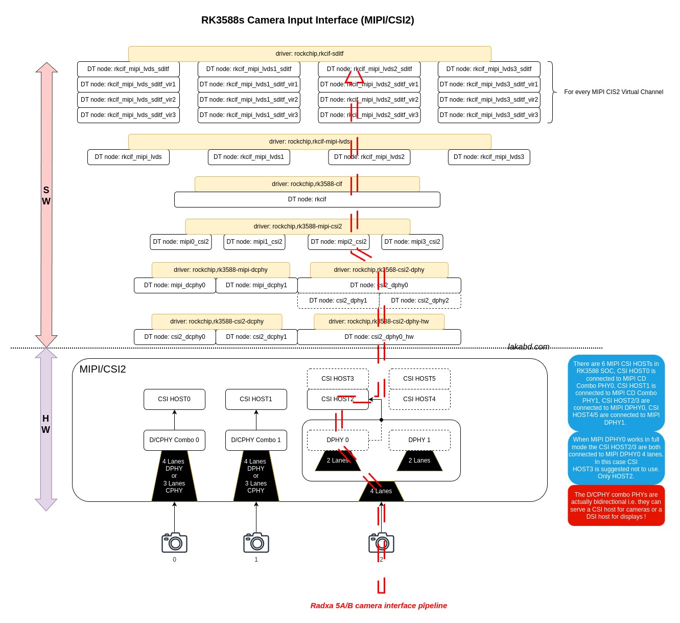
Below is the breakdown of all the drivers involved in this marvellous work, with special focus on the V4L2 / Media Controller implementation.
Note: the analysis doesn’t extend beyond the init processs (probing of the driver). The author considers that it would be insane to do otherwise !
Driver: rockchip,rk3588-csi2-dphy-hw
Kconfig: CONFIG_PHY_ROCKCHIP_CSI2_DPHY
file: drivers/phy/rockchip/phy-rockchip-csi2-dphy-hw.c
DT:
csi2_dphy0_hw: csi2-dphy0-hw@fedc0000 {
compatible = "rockchip,rk3588-csi2-dphy-hw";
reg = <0x0 0xfedc0000 0x0 0x8000>;
clocks = <&cru PCLK_CSIPHY0>;
clock-names = "pclk";
resets = <&cru SRST_CSIPHY0>, <&cru SRST_P_CSIPHY0>;
reset-names = "srst_csiphy0", "srst_p_csiphy0";
rockchip,grf = <&mipidphy0_grf>;
rockchip,sys_grf = <&sys_grf>;
status = "disabled";
};
- This driver is used for low level interactions with the DPhy HW
- Defines necessary routines for starting and stopping the stream
Driver: rockchip,rk3568-csi2-dphy
Kconfig = CONFIG_PHY_ROCKCHIP_CSI2_DPHY
file: drivers/phy/rockchip/phy-rockchip-csi2-dphy.c
DT
/* dphy0 full mode */
csi2_dphy0: csi2-dphy0 {
compatible = "rockchip,rk3568-csi2-dphy";
rockchip,hw = <&csi2_dphy0_hw>;
status = "okay";
ports {
#address-cells = <1>;
#size-cells = <0>;
port@0 {
reg = <0>;
#address-cells = <1>;
#size-cells = <0>;
mipidphy0_in_ucam0: endpoint@1 {
reg = <1>;
remote-endpoint = <&imx415_out0>;
data-lanes = <1 2 3 4>;
};
};
port@1 {
reg = <1>;
#address-cells = <1>;
#size-cells = <0>;
csidphy0_out: endpoint@0 {
reg = <0>;
remote-endpoint = <&mipi2_csi2_input>;
};
};
};
};
- rockchip_csi2_dphy_probe:
- rockchip_csi2_dphy_attach_hw: get associated DPhy HW driver pdata from "rockchip,hw" phandle
- v4l2_subdev_init: initializes a v4l2 subdevice for the DPHY interface with the following ops.
- .core = {.s_power}
- .video = {.g_frame_interval, .s_stream}
- .pad = {.set_fmt, .get_fmt, .get_selection, .get_mbus_config}
This subdevice requests to have a device node in user space: sd->flags |= V4L2_SUBDEV_FL_HAS_DEVNODE
- rockchip_csi2dphy_media_init:
- media_entity_pads_init(): initializes the subdevice as media entity with two pads (sink and source) and defines the entity role to be a “video interface bridge”
- v4l2_async_notifier_parse_fwnode_endpoints_by_port():
- parses defined endpoints in port 0 in DT to fill 3 main bus configs:
- bus type: V4L2_MBUS_CSI2_DPHY (as this is a DPHY driver obviously). This is detected based on the properties defined in the endpoint e.g., data-lanes, clock-lanes…
- bus flags: mainly if to use continuous or non-continuous clocks (non-continuous applicable only for DPHY). Also detected from an endpoint property : clock-noncontinuous
- bus lanes: number of lanes that are needed. endpoint property data-lanes.
The interesting part is that these info are filled in a custom structure ‘sensor_async_subdev’ that holds together the v4l2_async_notifier (returned by the notifier), the v4l2_mbus_config along with an integer to store the # of lanes.
So ‘sensor_async_subdev’ is used to hold the bus info for the remote endpoint. This will be used later in .bound to link these info with the remote endpoint’s subdevice.
- v4l2_async_subdev_notifier_register(): registers a subdevice async notifier (to be notified when the other subdevices that are needed for the pipeline - defined in DTB by endpoint graphs get registered) with two notifier ops:
- .bound: gets called when a matching subdevice gets bound. This function accomplishes the following:
- fills in the driver’s csi2_sensor array (up to 2 sensors) with the new bound sensor data: the mbus config (got from ‘sensor_async_subdev’) and the sd pointer.
- media_create_pad_link: creates a media link between the sensor’s subdevice source pad and our dphy’s subdevice sink pad. and sets this link as MEDIA_LNK_FL_ENABLED.
- .unbind: remove sensor from the driver’s csi2_sensor array.
- v4l2_async_register_subdev(): registers the DPHY subdevice asynchronously.
Driver: rockchip,rk3588-mipi-csi2
Kconfig: CONFIG_VIDEO_ROCKCHIP_CIF
file: drivers/media/platform/rockchip/cif/mipi-csi2.c
DT:
mipi2_csi2: mipi2-csi2@fdd30000 {
compatible = "rockchip,rk3588-mipi-csi2";
reg = <0x0 0xfdd30000 0x0 0x10000>;
reg-names = "csihost_regs";
interrupts = <GIC_SPI 147 IRQ_TYPE_LEVEL_HIGH>,
<GIC_SPI 148 IRQ_TYPE_LEVEL_HIGH>;
interrupt-names = "csi-intr1", "csi-intr2";
clocks = <&cru PCLK_CSI_HOST_2>;
clock-names = "pclk_csi2host";
resets = <&cru SRST_P_CSI_HOST_2>, <&cru SRST_CSIHOST2_VICAP>;
reset-names = "srst_csihost_p", "srst_csihost_vicap";
status = "okay";
ports {
#address-cells = <1>;
#size-cells = <0>;
port@0 {
reg = <0>;
#address-cells = <1>;
#size-cells = <0>;
mipi2_csi2_input: endpoint@1 {
reg = <1>;
remote-endpoint = <&csidphy0_out>;
};
};
port@1 {
reg = <1>;
#address-cells = <1>;
#size-cells = <0>;
mipi2_csi2_output: endpoint@0 {
reg = <0>;
remote-endpoint = <&cif_mipi2_in0>;
};
};
};
};
This subdevice requests to have a device node in user space: sd->flags |= V4L2_SUBDEV_FL_HAS_DEVNODE
media_entity_pads_init()
Looking closely at the driver, it turned out that the bus info is retrieved directly from the remote endpoint, when the link is live, using the registered op get_mbus_config ! The remote endpoint in our case is the DPHY subdevice.
v4l2_async_notifier_init()
v4l2_async_notifier_parse_fwnode_endpoints_by_port()
v4l2_async_subdev_notifier_register()
v4l2_async_register_subdev()
Driver: rockchip,rk3588-cif
Kconfig: CONFIG_VIDEO_ROCKCHIP_CIF
file: drivers/media/platform/rockchip/cif/hw.c
DT:
rkcif: rkcif@fdce0000 {
compatible = "rockchip,rk3588-cif";
reg = <0x0 0xfdce0000 0x0 0x800>;
reg-names = "cif_regs";
interrupts = <GIC_SPI 155 IRQ_TYPE_LEVEL_HIGH>;
interrupt-names = "cif-intr";
clocks = <&cru ACLK_VICAP>, <&cru HCLK_VICAP>, <&cru DCLK_VICAP>;
clock-names = "aclk_cif", "hclk_cif", "dclk_cif";
resets = <&cru SRST_A_VICAP>, <&cru SRST_H_VICAP>, <&cru SRST_D_VICAP>;
reset-names = "rst_cif_a", "rst_cif_h", "rst_cif_d";
assigned-clocks = <&cru DCLK_VICAP>;
assigned-clock-rates = <600000000>;
power-domains = <&power RK3588_PD_VI>;
rockchip,grf = <&sys_grf>;
iommus = <&rkcif_mmu>;
status = "disabled";
};
- rkcif_plat_hw_probe:
- configures the video capture device: get clk, reset, irq and iommu (it uses VB2 CMA Scatter-Gather allocator vb2_cma_sg_memops) !
- rkcif_csi2_register_notifier:
- register a notifier reset callback rkcif_reset_notifier() into a CSI2 notifier chain created in the mipi CSI2 host driver (ATOMIC_NOTIFIER_HEAD(g_csi_host_chain)).
This basically says: “Hey CSI2 host, if a reset event happens, please call my reset callback.”
Driver: rockchip,rkcif-mipi-lvds : “I have the ring !”
Kconfig: CONFIG_VIDEO_ROCKCHIP_CIF
file: drivers/media/platform/rockchip/cif/dev.c
DT:
rkcif_mipi_lvds2: rkcif-mipi-lvds {
compatible = "rockchip,rkcif-mipi-lvds";
rockchip,hw = <&rkcif>;
iommus = <&rkcif_mmu>;
status = "okay";
port {
cif_mipi2_in0: endpoint {
remote-endpoint = <&mipi2_csi2_output>;
};
};
};
rkcif_plat_probe:
- rkcif_attach_hw: get &rkcif dev data (regsitred in previous driver)
- rkcif_plat_init:
- init locks and counters:
- stream_lock, scale_lock, tools_lock, hdr_lock, buffree_lock
- pipe.power_cnt: Keeps track if the pipeline is already powered on to not power it again.
- pipe.stream_cnt: Tracks how many users are streaming video through the pipe.
- power_cnt: Similar to pipe.power_cnt, but dedicated to the whole CIF suspend/resume.
- init rkcif pipeline: This reflects the whole capture pipeline managed by this driver. This pipeline consists of the media controller chain from the camera entity till the CIF entity. The following are the functions that are defined to manage this pipline:
- pipe.open: Discover all upstream subdevices in the media graph and fill the pipeline’s subdevice list.
- pipe.close: Tear down the pipeline. it actually just decrements the pipe.power_cnt.
- pipe.set_stream: Start or stop the video streaming. It actually calls the s_stream from video ops of each subdevice in the pipeline’s list.
- rkcif_stream_init(): initializes the rkcif_stream structure which is the core structure that encapsulates all that is needed to run/control a stream. One interesting member of this struct is the rkcif_vdev_node structure. This node holds the main skeleton objects:
- The vb2_queue: This is the videobuf2 queue that handles the actual DMA buffers exchanged with user space.
- The video_device: This represents the actual v4l2 video node that user space sees as /dev/videoX
- The media_pad: This is the media controller pad that connects this video node to the rest of the pipeline graph.
- There are 4 streams/MIPI channels i.e., This function is called for every MIPI vc 0, 1, 2 and 3
- rkcif_init_scale_vdev(): initializes a scaling video device (vdev) for the scaling hw block in the CIF
- This function is called for every MIPI vc as there are 4 scaling blocs
- rkcif_init_tools_vdev(): Initializes the tool’s vdev for internal debugging !
- only 3 channels/vdevs are created.
- v4l2_device_register(): registers the rkcif v4l2 device container (this can be seen as the parent of all video devices in the rkcif pipeline)
- media_device_register(): registers the rkcif media device for representing the whole rkcif graph. This media device is linked to the v4l2 device as such v4l2_dev->mdev = &cif_dev->media_dev. This one assignment makes every media entity, pad or link that gets created from now on, for a subdevice/vdev that belongs to this v4l2 device, to be included in this media device’s graph automatically.
- rkcif_register_platform_subdevs():
- rkcif_register_stream_vdevs():
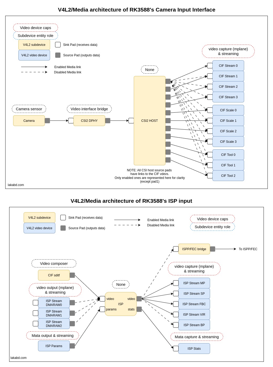
- registers 4 video devices (/dev/video0,1,2,3) one for every MIPI CSI2 channel.
- vdev->device_caps = V4L2_CAP_VIDEO_CAPTURE_MPLANE |
V4L2_CAP_STREAMING - sets up the bv2 buffer queue for every vdev with the mem_ops as defined in the hw driver i.e., vb2_cma_sg_memops supporting MMAP and DMA_BUF transfer modes.
- Each vdev is associated with a media entity with only one sink pad. (this entity represents the head of the graph)
- rkcif_register_scale_vdevs(): similar to stream vdev
- rkcif_register_tools_vdevs(): similar to stream vdev
- initializes a complete object cif_dev->cmpl_ntf and runs a kernel thread for the notifier_isp_thread(). This thread will wait for this complete object to be signaled.
- cif_subdev_notifier:
- v4l2_async_notifier_parse_fwnode_endpoints:
- parses all child ports in DT and for each one a v4l2_async_subdev is allocated and the existing endpoints are parsed to get the bus type, the bus flags and the number of lanes the bus needs (as done in the DPHY driver - but in that case _by_port() function was used and only port0 was parsed).
- v4l2_async_notifier_register: registers a v4l2 device async notifier with two notifier ops: bound and complete:
(One very important remark regarding this function is that before the bound callback is called, it internally calls v4l2_device_register_subdev() to register the subdevice it found with the v4l2 device !)
- .bound=subdev_notifier_bound: gets called when the linked subdevice (in DT endpoint graph) is bound. This function saves the number of subdevices/sensors bound to the cif and their info e.g., num lanes, mbus settings. radxa 5a: The awaited sd is the one and only MIPI CSI2 host 2 subdevice.
- .complete=subdev_notifier_complete: gets called when all linked subdevices are successfully registered. This function does the following:
- for each registered sensor in the v4l2_device it calls its subdev’s get_mbus_config() pad op to get the number of lanes (for CSI2 sensors)
- rkcif_create_links: This one creates a Bunch of media links. Basically:
- For each registered sensor/subdevice; do
- For each source pad in the subdevice; do
- Create 4 media links, one for every stream video device.
- Create 4 media links, one for every scale video device.
- Create 3 media links, one for every tool video device.
- By default, not all these links are enabled (total of 11 * 11 = 121 links for the remote mipi CSI2 host subdevice). Only the following are set to MEDIA_LNK_FL_ENABLED
- remote_pad[1] → stream[0]
- remote_pad[2] → stream[1]
- remote_pad[3] → stream[2]
- remote_pad[4] → stream[3]
- remote_pad[5] → scale[0]
- remote_pad[6] → scale[1]
- remote_pad[7] → scale[2]
- remote_pad[8] → scale[3]
- remote_pad[9] → tools[0]
- remote_pad[10] → tools[1]
- remote_pad[11] → tools[2]
Note that the index for remote doesn't start at 0, that’s because the pad 0 is the sink pad !
- v4l2_device_register_subdev_nodes(): For all subdevices under the v4l2_device it creates /dev/v4l-subdev* nodes for those that asked.
- _set_pipeline_default_fmt(): initializes the default video format for each CIF stream
- get the camera sensor subdevice from stream[0] pad and fill in the terminal_sensor member of the rkcif device with the camera’s sd and other info such as the mbus, #lanes, name …etc. In order to find the camera sensor, the media_graph_walk_* set of functions are used on the stream[0]’s entity. These functions are used to scan the whole media graph looking for entities with entity->function equal to MEDIA_ENT_F_CAM_SENSOR.
In this step we also set the active_sensor member to the remote sensor linked to stream[0] pad. radxa 5a: This is the MIPI CSI2 host 2. - For every CIF stream, it queries the terminal_sensor for its native format and dimensions via sensor pad ops:
- .get_fmt (.which=V4L2_SUBDEV_FORMAT_ACTIVE): get sensor format and resolution.
- .get_selection (.which=V4L2_SEL_TGT_CROP_BOUNDS ): get crop bounds i.e., portion of the sensor’s image that is usable, so CIF doesn’t assume a larger frame than the sensor can deliver.
- sets the v4l2_pix_format_mplane accordingly for every stream
- signal the complete object cif_dev->cmpl_ntf to enable the notifier_isp_thread()
- notifier_isp_thread():
- subdev_asyn_register_itf():
- v4l2_async_register_subdev_sensor_common: registers asynchronously the first sditf subdevice from the rkcif device array cif_dev->->sditf. This array is filled with subdevices in the sditf driver.
WHY register only the first subdevice ???
WHY is this called in the first place, no media link exists between the rkcif and sditf ???
- adds the current cif device to the rkcif_device_list.
- rkcif_proc_init: Creates /proc/rkcif* entry to get driver and camera details in user-space.
Driver: rockchip,rkcif-sditf
Kconfig: CONFIG_VIDEO_ROCKCHIP_CIF
file: drivers/media/platform/rockchip/cif/subdev-itf.c
DT:
rkcif_mipi_lvds2_sditf: rkcif-mipi-lvds2-sditf {
compatible = "rockchip,rkcif-sditf";
rockchip,cif = <&rkcif_mipi_lvds2>;
status = "okay";
port {
mipi_lvds2_sditf: endpoint {
remote-endpoint = <&isp0_vir0>;
};
};
};
rkcif_subdev_probe:
- v4l2_subdev_init: Initializes the sditf (subdevice interface!!) v4l2 subdevice:
- .core = {.s_power, .ioctl}
- .video = {.g_frame_interval, .s_stream, .s_rx_buffer}
- .pad = {.set_fmt, .get_fmt, .get_selection, .get_mbus_config}
This subdevice requests to have a device node in user space: sd->flags |= V4L2_SUBDEV_FL_HAS_DEVNODE
- rkcif_sditf_attach_cifdev: Get the rkcif device from the "rockchip,cif" phandle in DT, save it in sditf->cif_dev and more importantly, fills in the cif_dev->sditf array with the current subdevice and increment cif_dev->sditf_cnt. This makes the rkcif driver access sditf more easily.
- rkcif_subdev_media_init:
- media_entity_pads_init: Initializes a media entity as a MEDIA_ENT_F_PROC_VIDEO_COMPOSER with only one source pad ! (a source for the ISP). V4L2 doc says: An entity capable of video composing must have at least two sink pads and one source pad.
- v4l2_ctrl_handler_init: Allocates a control handler for this subdev
- v4l2_ctrl_new_std:
- Adds a pixel rate control (V4L2_CID_PIXEL_RATE) → user-space can set the pixel rate of the camera sensor. (it calls the ctrl_handler of the cif_dev->terminal_sensor filled in the rkcif driver)
- Marks it volatile, meaning its value can change dynamically (depends on sensor mode, not fixed).
- Initializes the isp info toisp_inf : channels state and link mode.
- INIT_WORK: Initializes a kernel worker for a deferred cleanup mechanism.
- sditf_buffree_work: loops through buffers to free in list sditf_priv->buf_free_list and free them by calling rkcif_free_reserved_mem_buf()
NOTE: we don’t register the subdevice here ! it is registered asynchronously in the rkcif driver
Driver: sony,imx415
Kconfig: CONFIG_VIDEO_IMX415
file: drivers\media\i2c\imx415.c
DT:
imx415: imx415@1a {
status = "disabled";
compatible = "sony,imx415";
reg = <0x1a>;
clocks = <&cru CLK_MIPI_CAMARAOUT_M2>;
clock-names = "xvclk";
pinctrl-names = "default";
pinctrl-0 = <&mipim0_camera2_clk>;
power-domains = <&power RK3588_PD_VI>;
pwdn-gpios = <&gpio1 RK_PD3 GPIO_ACTIVE_HIGH>;
reset-gpios = <&gpio1 RK_PD2 GPIO_ACTIVE_LOW>;
rockchip,camera-module-index = <0>;
rockchip,camera-module-facing = "back";
rockchip,camera-module-name = "RADXA-CAMERA-4K";
rockchip,camera-module-lens-name = "DEFAULT";
port {
imx415_out0: endpoint {
remote-endpoint = <&mipidphy0_in_ucam0>;
data-lanes = <1 2 3 4>;
};
};
};
imx415_probe:
- Parse camera modes from DT: rockhip specific camera accessory infos and if HDR is to be enabled.
- Set the camera mode settings according to hdr info: bus_fmt, resolution, max_fps… what are these mode settings:
- .bus_fmt = MEDIA_BUS_FMT_SGBRG10_1X10: indicates a Bayer pattern format. Specifically, it's a 10-bit SGBRG (Staggered Green-Blue-Red-Green) pattern, where each pixel is represented by 10 bits. The 1X10 part means that each pixel is transferred in one 10-bits sample. In a Bayer pattern, each pixel only captures one color (Red, Green, or Blue), and a full-color image is reconstructed through debayering.
- .width = 3864: number of effective pixels in width
- .height = 2192: number of effective pixels in height
- .max_fps = {.numerator = 10000, .denominator = 300000}: This defines the maximum frame rate. It means the maximum frame rate is 1/30 frames per second or approximately 30 frames per second. This is a common way to represent frame rates accurately without floating-point numbers.
- .vts_def = 0x08ca: Vertical TIme Setting in number of horizontal lines. In the datasheet it’s called VMAX or frame period. This is the total number of lines in a single frame. This value is inversely proportional to the sensor’s FPS.
- .hts_def = 0x044c * IMX415_4LANES * 2: Horizontal Time Setting in number of clocks per line. This is the total number of clocks per line. 0x044c is the value written into HMAX reg.
- HMAX reg calculation and impact is not clear at all in the datasheet. The number of CSI2 Lanes is inversely proportional to the number of cycles per line, but here we see the inverse. The times *2 multiplication is also so alien to me rn.
- .exp_def = 0x08ca - 0x08: This is the sensor’s exposure time in number of lines.
- .hdr_mode = NO_HDR: The imx415 is capable of High Dynamic Range capture. The driver supports Digital Overlap HDR for single frame 2 (Long and Medium) and 3 exposures (Long, Medium and Short).
- .vc[PAD0]: this is the virtual channel id that the sensor’s CSI2 phy will use. In HDR mode, different exposures are transmitted in distinct virtual channels.
- get xvclk (the SoC master clk for the camera), power gpio and reset gpio from DT.
- imx415_configure_regulators(): no supply defined in DT, dummy reguls are used.
- v4l2_i2c_subdev_init: initializes a v4l2 subdevice with the sensor’s i2c client name and pdata. It is initialized with the following ops:
- .core = {.s_power, .ioctl}
- .video = {.g_frame_interval, .s_stream}
- .pad = {.set_fmt, .get_fmt, .get_selection, .get_mbus_config, .enum_mbus_code, .enum_frame_size, .enum_frame_interval}
- imx415_initialize_controls:
- v4l2_ctrl_handler_init: initializes a control handler with 8 controls. This handler will be set into imx415->subdev.ctrl_handler.
- imx415->link_freq = v4l2_ctrl_new_int_menu(): This initializes a MIPI link frequency control V4L2_CID_LINK_FREQ. The menu values are defined in the link_freq_items array and it defines the following clocks: 297, 446, 743, 891MHz. This ctrl doesn’t make sense as the mipi frequency cannot be independently changed in regards to the other mode settings of the camera e.g., fps.
- imx415->pixel_rate = v4l2_ctrl_new_std(): Defines a read-only pixel rate control V4L2_CID_PIXEL_RATE. This ctrl returns the current configured pixel rate as per the formula: pixel rate = (link frequency / bpp) * 2 * lanes (for the 1st mode = 446MHz / 10 * 2 * 4 = 356.8 MegaPixel/s)
NOTE: the multiplication by 2 is because MIPI CSI2 uses DDR mode (double data rate mode) i.e., data is sampled in both rising and falling edges of the clock. And the multiplication by the number of lanes is because the link freq is per lane i.e., the more lanes you use the more pixels you transfer. - imx415->hblank = v4l2_ctrl_new_std(): Defines a read-only horizontal blank control V4L2_CID_HBLANK. h_blank = mode->hts_def - mode->width.
- imx415->vblank = v4l2_ctrl_new_std(): Defines a read-write vertical blank control V4L2_CID_VBLANK. vblank_def = mode->vts_def - mode->height. The .s_ctrl ops for this control is defined in imx415_set_ctrl.
- imx415->exposure = v4l2_ctrl_new_std(): Defines a read-write exposure control V4L2_CID_EXPOSURE. The .s_ctrl ops for this control is defined in imx415_set_ctrl.
- imx415->anal_a_gain = v4l2_ctrl_new_std(): Defines a read-write analogue gain control V4L2_CID_EXPOSURE. The .s_ctrl ops for this control is defined in imx415_set_ctrl. This ctrl is available only for NO_HDR mode.
- V4L2_CID_HFLIP: Defines a read-write horizontal flip control.
- V4L2_CID_VFLIP: Defines a read-write vertical flip control.
- __imx415_power_on(): power on the camera:
- enable power gpio
- disable reset gpio
- enable xvclk at a freq = 37.125MHz
- imx415_check_sensor_id(): sensor identification
- media_entity_pads_init():
- Initializes the subdev’s entity as a MEDIA_ENT_F_CAM_SENSOR with only one source pad.
- v4l2_async_register_subdev_sensor_common:
- register the imx415 subdevice asynchronously.
- sd flags: V4L2_SUBDEV_FL_HAS_DEVNODE (to have a /dev/v4l-subdev*) and V4L2_SUBDEV_FL_HAS_EVENTS (to be able to generate async events)
- internal_ops: .open is defined in imx415_open(). This op is called by the v4l2 framework when /dev/v4l-subdev* is opened. imx415_open() fills the try_fmt format of the subdev’s source pad with the sensor’s default format.
NOTE1: try_fmt is a sandboxed copy of the format for each file handle i.e., for every app that opens the sd. This sandboxing mechanism is necessary so that format negotiation doesn’t affect the active settings of the sensor. The user space app can negotiate sensor format using the following calls: VIDIOC_SUBDEV_G_FMT(..., V4L2_SUBDEV_FORMAT_TRY) and VIDIOC_SUBDEV_S_FMT(..., V4L2_SUBDEV_FORMAT_TRY). Once the negotiation ends, the app can set the final format as active by calling: VIDIOC_SUBDEV_S_FMT(..., V4L2_SUBDEV_FORMAT_ACTIVE).
NOTE2: the difference between ops and internal ops:
sd->ops → external API operations (controls, video ops, pad ops, etc.).These are exposed to the media graph and ultimately to userspace.
sd->internal_ops → internal management callbacks, used by the V4L2 framework itself for subdev lifecycle, power, and state handling (device open, close, register…)
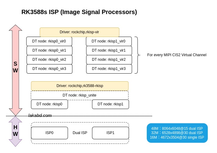
Driver: rockchip,rk3588-rkisp:
Kconfig: CONFIG_VIDEO_ROCKCHIP_ISP
file: drivers/media/platform/rockchip/isp/hw.c
DT:
rkisp0: rkisp@fdcb0000 {
compatible = "rockchip,rk3588-rkisp";
reg = <0x0 0xfdcb0000 0x0 0x7f00>;
interrupts = <GIC_SPI 131 IRQ_TYPE_LEVEL_HIGH>,
<GIC_SPI 133 IRQ_TYPE_LEVEL_HIGH>,
<GIC_SPI 134 IRQ_TYPE_LEVEL_HIGH>;
interrupt-names = "isp_irq", "mi_irq", "mipi_irq";
clocks = <&cru ACLK_ISP0>, <&cru HCLK_ISP0>,
<&cru CLK_ISP0_CORE>, <&cru CLK_ISP0_CORE_MARVIN>,
<&cru CLK_ISP0_CORE_VICAP>;
clock-names = "aclk_isp", "hclk_isp", "clk_isp_core",
"clk_isp_core_marvin", "clk_isp_core_vicap";
power-domains = <&power RK3588_PD_VI>;
iommus = <&isp0_mmu>;
status = "okay";
};
rkisp_hw_probe:
- of_property_read_u32_array(node, "max-input",...): from DT get max input widthxheight@fps
- get memory ressources (GRF, IORESOURCE_MEM)
- rkisp_register_irq(): register 3 irqs
- isp_irq → isp_irq_hdl(): Core ISP interrupt
- mi_irq → mi_irq_hdl(): Memory Interface interrupt. This memory iface block connects ISP output to DDR.
- mipi_irq → mipi_irq_hdl(): MIPI host interrupt
- set hw_dev->clk_rate_tbl which is the lookup table for the mapping of: ISP clock <-> input image width (bandwidth requirements).
- init hw_dev structure.
- is_iommu_enable(): verify that ISP’s iommu is enabled
- set hw_dev->mem_ops to VB2 CMA Scatter-Gather allocator vb2_cma_sg_memops (similar to rkcif).
Driver: rockchip,rkisp-vir:
Kconfig: CONFIG_VIDEO_ROCKCHIP_ISP
file: drivers/media/platform/rockchip/isp/dev.c
DT:
rkisp0_vir0: rkisp0-vir0 {
compatible = "rockchip,rkisp-vir";
rockchip,hw = <&rkisp0>;
status = "okay";
port {
#address-cells = <1>;
#size-cells = <0>;
isp0_vir0: endpoint@0 {
reg = <0>;
remote-endpoint = <&mipi_lvds2_sditf>;
};
};
};
rkisp_plat_probe:
- rkisp_attach_hw(): attach the hw_dev from ‘rockchip,hw’ phandle to the current rkisp_device isp->hw_dev = hw…
- Init the rkisp_pipeline: similar to the rkcif pipeline:
- pipe.open = rkisp_pipeline_open():
- __isp_pipeline_prepare(): walks the current device’s media graph and fills all subdevs it finds in the pipe->subdevs[8max] array (it also increments pipe->num_subdevs). radxa 5a: the linked subdev is the mipi_lvds2_sditf.
- __isp_pipeline_s_isp_clk():
- loop through the linked subdevices in pipe->subdevs[] array and get the first camera sensor or rkcif itf (radxa 5a: mipi_lvds2_sditf) subdevice i.e., sd->entity.function equals to MEDIA_ENT_F_CAM_SENSOR or MEDIA_ENT_F_PROC_VIDEO_COMPOSER
- v4l2_ctrl_find(sd->ctrl_handler, V4L2_CID_PIXEL_RATE): get the pixel rate control of that device. (if none, quite with error).
- get the current pixel rate of the subdevice and calculate the ISP data rate in bytes/s as per the equation: (pixel_rate * bus_width)/8 where bus_width corresponds to bpp.
imx415 Camera (1st mode): date rate = 356.8Mpixels/s * 10bpp = 3.5Gbits/s or 446MBytes/s - adds 25% margin to the required data rate for safer operation.
- gets the minimum required ISP freq for the calculated data rate from the hw_dev->clk_rate_tbl lookup table and set it into ACLK.
- rkisp_csi_config_patch():
- rkisp_csi_get_hdr_cfg(): gets the hdr configuration from the linked composer subdevice (radxa 5a: as we are connected to the RKCIF i.e., dev->isp_inp == INP_CIF) by calling RKMODULE_GET_HDR_CFG ioctl. radxa 5a: this is defined in the ioctl core ops of the RKCIF’s sditf. RKMODULE_GET_HDR_CFG ioctl is actually forwarded to the cif_dev->terminal_sensor.sd which is the camera sensor’s subdevice !! (recall that the terminal_sensor is filled/found in .complete callback of the CIF’s v4l2 device’s async notifier).
For the IMX415, this ioctl actually returns that the hdr_esp_mode is HDR_NORMAL_VC i.e., hdr frame with diff virtual channels and returns the hdr_mode of the currently selected imx415 mode (default mode has hdr disabled=0 → NO_HDR/HDR_NORMAL). - Continues to the low level HDR configuration.
- pipe.close = rkisp_pipeline_close(): calls rkisp_rx_buf_pool_free() to free all reserved buffers.
- pipe.set_stream = rkisp_pipeline_set_stream(): set stream on/off. Calls the subdevice’s video s_stream ops. ON: sd(ISP) -> sd (rkcif…mipi dphy) -> sd(camera).
- v4l2_ctrl_handler_init(): initializes the ISP’s control handler with max 5 controls.
- v4l2_device_register(): registers a v4l2 device for the ISP
- media_device_init(): Initializes the ISP’s media device wthe the following ops:
- .link_notify = v4l2_pipeline_link_notify(): a V4L2 mc function to propagate link status changes (enabled/disabled) to connected entities.
- media_device_register(): register the ISP’s media device. This mdev is linked to the previously registered V4L2 device:
isp_dev->v4l2_dev->mdev = &isp_dev->media_dev. - rkisp_register_platform_subdevs():
- rkisp_register_isp_subdev(): Creates the ISP’s V4L2 subdevice:
- v4l2_subdev_init(): initializes the subdevice with the following ops:
- .core = {.subscribe_event, .unsubscribe_event, .s_power, .ioctl}
- .video = {.s_rx_buffer, .s_stream}
- .pad = {.set_fmt, .get_fmt, .get_selection, .set_selection, .enum_mbus_code, .link_validate}
- sets the subdevice’s flag to V4L2_SUBDEV_FL_HAS_DEVNODE (/dev/v4l-subdev*) | V4L2_SUBDEV_FL_HAS_EVENTS (to generate events)
- media_entity_pads_init():
- Initializes the sd’s entity as generic (MEDIA_ENT_F_V4L2_SUBDEV_UNKNOWN) with the following ops:
- .link_setup = rkisp_subdev_link_setup(): TODO
- .link_validate = rkisp_subdev_link_validate(): TODO
- 4 pads are defined for this entity:
- SINK pad → receives image data.
- SINK_PARAMS pad → configuration/tuning input.
- SOURCE_PATH pad → processed video output.
- SOURCE_STATS pad → statistics output.
- sd->owner = THIS_MODULE: Sets the module ownership of the subdevice. This prevents unloading the module while this sd is still registered.
- v4l2_device_register_subdev(v4l2_dev, sd): registers this sd with the ISP’s v4l2 device.
- rkisp_isp_sd_init_default_fmt(): initializes the default in&out cropping and in&out format for the sd.
- rkisp_monitor_init(): initializes a monitor routine. ISP_V30/rk3588 not concerned.
- tasklet_init(): initializes a tasklet for rkisp_rdbk_task(). This tasklet is scheduled by the ISP and MI irqs to do the heavy lifting outside the ISR - that consists most likely of:
- Reading statistics from ISP (histograms, auto-exposure/white-balance/AWB stats).
- Reading capture metadata (HDR exposure info, CSI trigger events, etc.).
- rkisp_register_csi_subdev(): For ISP_V30/rk3588 this only initializes a subdev, it doesn’t register it ! (maybe because a CSI2 subdev does already exist - registered by the mipi host driver).
- This sd is initialized with the following ops:
- .core = {.s_power}
- .video = {.s_stream}
- .pad = {.set_fmt, .get_fmt, .get_mbus_config}
- The fact that this sd is not registered means that it will not be usable in user-space, but I think it still can be usable internally, as it is linked to the ISP device. (the fact that the version check is not done at the start of this function confirms this)
csi_dev->ispdev = rkisp_dev;
- rkisp_register_bridge_subdev(): This registers a bridge sd/media link between the ISP subdevice and the ISPP (Post Processor - From rm it seems that this is actually the FishEye Correction processor). This function works only when a remote endpoint to the ISPP is defined in DT.
- This sd is initialized with the following ops:
- .core = {.s_power, .ioctl}
- .video = {.s_stream, .s_rx_buffer}
- .pad = {.set_fmt, .get_fmt, .get_selection, .set_selection}
- v4l2_device_register_subdev(): registers the sd with only one media sink pad.
- media_create_pad_link(): creates a hard link with the ISP’s sd main video output pad RKISP_ISP_PAD_SOURCE_PATH and enables it.
- rkisp_register_stream_vdevs(): for ISP_V30/rk3588 it does the following:
- Sets the max width & height for the main path stream to 4672x3504 (non-isp-unite mode).
- rkisp_register_stream_v30(): This function registers the following stream paths of the ISP:
RKISP_STREAM_MP → Main Path (full-resolution output)
RKISP_STREAM_SP → Self Path (secondary, usually lower-res or cropped stream)
RKISP_STREAM_FBC → Frame Buffer Compression output stream
RKISP_STREAM_VIR → Virtual stream for tools or IQ analysis (_iqtool)
RKISP_STREAM_BP (disabled by default) → Bypass Path stream (alternative output, usually raw or statistics)
- rkisp_stream_init(dev, RKISP_STREAM_MP):
- fills the rkisp_stream struct of the current rkisp device (rkisp_dev->cap_dev->stream[id]) with the following:
- stream->id: RKISP_STREAM_MP
- stream->ops: stream management ops: .config_mi, .enable_mi, .disable_mi, .set_data_path, .is_stream_stopped, .update_mi and .frame_end.
- stream->config: a table of size constraints and register mappings for low level config of the path.
- stream->config->fmts: a table of supported formats in the path.
- rkisp_init_vb2_queue(): Initializes the video device’s VB2 buf_queue of the stream. This buf_queue uses the mem_ops of the hw_dev initialized in hw.c i.e., vb2_cma_sg_memops.
- rkisp_register_stream_vdev():
- video_register_device(): registers a video device (VFL_TYPE_VIDEO) for the current stream with the following ops:
- ioctl_ops: issuable on /dev/videoX in user-space via VIDIOC_* ioctls
- .vidioc_reqbufs = vb2_ioctl_reqbufs → Allocate/release buffer queues.
- .vidioc_querybuf = vb2_ioctl_querybuf → Query information about a buffer.
- .vidioc_create_bufs = vb2_ioctl_create_bufs → Dynamically create buffers.
- .vidioc_qbuf = vb2_ioctl_qbuf → Queue a buffer to the driver for capture.
- .vidioc_expbuf = vb2_ioctl_expbuf → Export a buffer as a DMABUF (for zero-copy sharing).
- .vidioc_dqbuf = vb2_ioctl_dqbuf → Dequeue a filled buffer back to user space.
- .vidioc_prepare_buf = vb2_ioctl_prepare_buf → Prepare buffer before queuing (optional).
- .vidioc_streamon = vb2_ioctl_streamon → Start streaming.
- .vidioc_streamoff = vb2_ioctl_streamoff → Stop streaming.
- fops: file operations on /dev/videoX
- .open = rkisp_fh_open → Called when user-space does open("/dev/videoX").
- .release = rkisp_fop_release → Called on close(fd).
- .unlocked_ioctl = video_ioctl2 → Central V4L2 ioctl dispatcher.
- .compat_ioctl32 = video_ioctl2 → Same as above, but handles 32-bit applications running on a 64-bit kernel (structure size/alignment fixes).
- .poll = vb2_fop_poll → Used by poll()/select()/epoll() in user-space.
- .mmap = vb2_fop_mmap → Handles mmap() from user-space, so buffers allocated in the kernel can be mapped directly into user space.
- And the following capabilities device_caps:
- V4L2_CAP_VIDEO_CAPTURE_MPLANE: This is a capture device compatible with multi-planar buffers
- V4L2_CAP_STREAMING: Means the device supports the streaming I/O model (VIDIOC_REQBUFS, VIDIOC_QBUF, VIDIOC_DQBUF).
- vdev->vfl_dir = VFL_DIR_RX: This is a receive video device (hardware → user-space)
- media_entity_pads_init(): initializes the video device’s entity pads with only one sink pad.
- media_create_pad_link(): Creates a hard link between the ISP’s sd RKISP_ISP_PAD_SOURCE_PATH pad and the current vdev sink pad. This link is enabled by default.
- tasklet_init(): Initializes rkisp_buf_done_task() tsaklet. This tasklet handles no-more used buffers by de-queuing them and handing them back to vb2: vb2_buffer_done(&vb2_buf, VB2_BUF_STATE_DONE).
- rkisp_stream_init(dev, RKISP_STREAM_SP): similar to above.
- rkisp_stream_init(dev, RKISP_STREAM_FBC): similar to above.
- rkisp_stream_init(dev, RKISP_STREAM_VIR): similar to above. But with no stream->ops as this is only a virtual path. Also, this uses the same stream->config as the main path.
- rkisp_register_dmarx_vdev(): This function registers the DMA Read (DMARX) input streams of the ISP (i.e., when the ISP reads frames directly from system memory). For ISP_V30/rk3588, it registers 3 paths:
RKISP_STREAM_RAWRD0: RAW Read channel 0 (from the vdev name “rkisp_rawrd0_m” this path is likely for HDR Medium exposure).
RKISP_STREAM_RAWRD1: RAW Read channel 1 (from the vdev name “rkisp_rawrd1_l” this path is likely for HDR Long exposure).
RKISP_STREAM_RAWRD2: RAW Read channel 2 (from the vdev name “rkisp_rawrd2_s” this path is likely for HDR Short exposure).
- Defines stream->ops and stream->config for each of these streams.
- rkisp_register_dmarx_video(): registers a video device for every stream with only one source pad:
- vdev->vfl_dir = VFL_DIR_TX: This is a transmitting video device (user-space → hardware).
- vdev->device_caps =
- V4L2_CAP_VIDEO_OUTPUT_MPLANE: device can accept multi-planar frames from user-space (output to hardware).
- V4L2_CAP_STREAMING
- media_create_pad_link(): Creates a hard link between the ISP’s sd RKISP_ISP_PAD_SINK pad and every DMARX stream’s vdev source pad. These 3 links are disabled by default.
- rkisp_register_stats_vdev():
- registers a video device for statistical data output from the isp. The RKISP outputs the 3A (auto focus, auto exposure and auto white balance) statistics, and also histogram statistics for the raw frames that are being processed:
- vdev->device_caps = V4L2_CAP_META_CAPTURE | V4L2_CAP_STREAMING: the device produces metadata buffers rather than standard video frame
- The vdev’s entity has only one sink pad.
- media_create_pad_link(): Creates a hard link between the ISP’s sd RKISP_ISP_PAD_SOURCE_STATS pad and the current vdev sink pad. This link is enabled by default.
- rtasklet_init(): registers a tasklet for sending statics data back to user space when ready. This tasklet is not used for ISP_V30 (data is directly sent to user-space in the stats ISR).
- rkisp_register_params_vdev():
- registers a video device for config params of the ISP. The RKISP’s parameter input is used for tuning the internal image processing e.g., black level correction… to enhance the video stream quality.
- vdev->device_caps = V4L2_CAP_STREAMING | V4L2_CAP_META_OUTPUT: The device captures params from user-space and sends them to the hardware.
- The vdev’s entity has only one source pad.
- media_create_pad_link(): Creates a hard link between the ISP’s sd RKISP_ISP_PAD_SINK_PARAMS pad and the current vdev source pad. This link is enabled by default.
- rkisp_register_luma_vdev(): Luma statistics video device. Not used for ISP_V30.
- isp_subdev_notifier():
- v4l2_async_notifier_parse_fwnode_endpoints:
- parses all child ports in DT and for each one a v4l2_async_subdev is allocated and the existing endpoints are parsed. For CSI2 sensors i.e., .bus_type == V4L2_MBUS_CSI2_DPHY/CPHY nothing is parsed from the endpoint as the child node is not a sensor (the child is the RKCIF in our case).
- v4l2_async_notifier_register: registers a v4l2 device async notifier with three notifier ops: bound, unbound and complete:
- .bound=subdev_notifier_bound: gets called when the linked subdevice (in DT endpoint graph) is bound. This function saves the subdevices/sensors bound to the ISP and their mbus info in the isp_dev->sensors[4] array. radxa 5a: The awaited sd is the RKCIF’s sditf of the CSI2 channel0 of the 3rd MIPI CSI2 host: mipi_lvds2_sditf.
- .unbound: called when a linked sd is unbound. This op calls the .link_setup of the RKISP sd with the unbound sd as argument, and removes the sd from isp_dev->sensors[] array.
- .complete=subdev_notifier_complete: gets called when all linked subdevices are successfully registered. This function does the following:
- rkisp_create_links(): loops through linked sensors/subdevices in isp_dev->sensors[] array, and for each one it finds the source pad and depending on the sd’s entity function (sensor, composer…) it links it with the ISP’s sd sink pad RKISP_ISP_PAD_SINK. radxa 5a: only one linked sd which is the rkcif sditf which is MEDIA_ENT_F_PROC_VIDEO_COMPOSER.
Also it is in this function that the ISP input type is set isp_dev->isp_inp. which is equal to INP_CIF for radxa 5a. - v4l2_device_register_subdev_nodes(): Registers a device node for every subdev (that is linked with the isp_dev->v4l2_device) marked with the V4L2_SUBDEV_FL_HAS_DEVNODE flag. These subdevs are: the ISP’s sd and sditf’s sd.
- rkisp_update_sensor_info(): Get the remote sensor subdev connected to the ISP’s sd sink pad (radxa 5a: this is the sditf) to query the current mbus config, the current format and the frame interval (fps) thes settings are stored in the isp’s sensor wrapper rkisp_sensor_info. This also sets this sd as the current active sensor isp_dev->active_sensor.
- _set_pipeline_default_fmt(): calls very long functions (a bit tired) to mainly check and configure the ISP’s fmt according to the info received from the remote sensor. For ISP_V30 the format is for the MP, FBC, RAWRD0,1,2 and BP.
- rkisp_proc_init(): return 0. Finally an eze one!
- Adds the ISP device to the rkisp_device_list…to keep track of initialized ISPs.
And tadaa: the full view of the V4L2/MC implementation